
PriWatt® Patented Busbar Anchoring System
Switchable glass rarely fails in the film. It fails at the connection.
The busbar, the conductive edge where the power supply meets the switchable layer, is the least discussed component in a PDLC panel and the one that decides how long the panel works. PriWatt’s answer to it is patented.
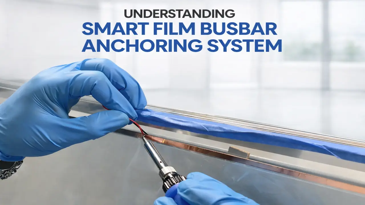
Why the edge is the weak point
PDLC works because a stable electrical field is held across the whole panel. In many conventional assemblies the busbar that delivers that field is bonded to the surface, left exposed to stress, and given no allowance for the glass expanding and contracting around it.
- Conductivity that comes and goes instead of staying constant
- Visible defects appearing along the edge of the panel
- Switching that degrades: slower, patchier, less even
- Failure well before the film itself is finished
None of that is a material problem. It is a connection problem, and it is solved by engineering the connection, not by buying better film.
Working on one now? Send the panel schedule, and we will show where the busbars sit and we will price the panels themselves — a quotation with the schedule, the transformer and the lead time on it. Rate cards do not survive contact with a real opening. Still deciding? Start with twenty minutes with a project specialist.
What PriWatt does instead
The anchoring system replaces surface adhesion with a reinforced, multi-layer structure that holds the busbar mechanically as well as electrically:
- A dedicated anchoring layer, carrying the load
- A conductive busbar interface, carrying the current
- A stabilised bonding structure holding the two in relation to each other
The busbar is locked into the structure of the film, not attached to it. Movement is resisted, pressure is distributed instead of concentrating at a point, and the current is delivered evenly along the whole edge.
Patented: US 11,686,966 B2 and Canada 3,212,838.
What that buys, panel by panel
Durability
- Less risk of delamination
- Fewer edge failures
- Electrical fatigue pushed further out
Stable switching
- Uniform switching across the panel
- No flicker and no dead zones
- The same behaviour from one end of the glass to the other
Room to move
Glass expands and contracts with temperature, every day, for as long as the building stands. The anchoring accommodates that movement without breaking the connection or degrading conductivity.
A cleaner edge
Because the connection is controlled instead of improvised, the finished panel has fewer visible defects along its edge, and the edge is where a specifier looks first.
What the patent actually claims
Anyone can read it. US 11,686,966 B2 is titled Busbar anchoring system and method for PDLC films, and the specification is public.
To follow it, one detail about how the film is built. A PDLC layup is a liquid-crystal layer flanked by two coatings of indium tin oxide, a transparent conductor. ITO is what makes the film switch and see through at the same time: it carries current across the whole surface while staying invisible. It is also a thin, hard, brittle oxide, and every amp that ever reaches the panel arrives through the joint between a metal busbar strip and that coating.
That joint is the problem. Bond a strip to the surface of an ITO coating and you are relying on adhesion between two materials that expand at different rates, through the heat and pressure of lamination and then through every hot afternoon the facade has.
What the patent describes is conductive mesh anchors bonded in between: interposed between the busbar strip and the ITO layer along the sections of the layup, adhesively coupled to both. The connection stops being a surface contact and becomes an interlocked one, with far more contact area carrying the current.
The Canadian counterpart is CA 3,212,838. Both numbers are on patents and certifications, and both can be looked up in a patent database in about a minute. That is the point of publishing them.
| Surface-bonded busbar | Anchored busbar | |
|---|---|---|
| What holds the connection | Adhesion to the face of the ITO coating | Conductive mesh anchors bonded between strip and coating |
| Contact area carrying current | The footprint of the strip | Multiplied by the mesh structure |
| Through lamination heat and pressure | The bond is the only thing resisting it | The anchors are mechanically interlocked |
| Under thermal cycling | Differential expansion works the joint | Movement is taken by the anchor structure |
| How it fails | Contact resistance rises at the edge, then switching goes patchy | The failure mode the system is designed out of |
Why it shows up only in real buildings
In a controlled environment most systems behave. What exposes a weak connection is ordinary service: temperature swinging through the year, the stress of being installed, and a few thousand switching cycles. Most smart film treats the busbar as an accessory; here it is treated as a structural component, and that decision is what the lifespan, the reliability and the consistency all rest on.
Patents and certifications
The patents in full, with UL and SGCC alongside them.
Smart film without UL
Why the same edge is the reason certification matters.
PriWatt PDLC film
The product the anchoring system is built into.
Common questions
The conductive strip along the edge of the panel that delivers power into the switchable layer. The film itself is transparent because it switches through coatings of indium tin oxide, and the busbar is where current crosses from a metal strip into those coatings. It is the smallest part of the panel and the one that decides its life.
Because that joint carries everything. A busbar bonded to the face of an ITO coating relies on adhesion between materials that expand at different rates, through lamination heat and then through years of thermal cycling. As contact resistance rises at the edge, switching goes slower and patchier before it goes altogether.
It puts conductive mesh anchors between the busbar strip and the ITO layer, bonded to both, so the connection is interlocked instead of stuck to a surface, and the current is carried across far more contact area. The patents are US 11,686,966 B2 and CA 3,212,838, and both can be read in full.
Yes, and that is why the numbers are published, not described. Search either number in any patent database. The US title is "Busbar anchoring system and method for PDLC films".
It matters most there. A fabricator puts the layup through their own autoclave, so the connection meets that heat and pressure inside somebody else’s process. How the busbar is handled is one of the four questions that decide whether a supply arrangement works.
No, and nothing certifies it. UL covers the electrical system and SGCC covers the safety glazing; neither tests how well a connection is anchored. That is engineering, not certification, and it is why the method is patented instead.
Specifying for the tenth year, not the first
Send the panel sizes or the drawings. The busbars are American and so is the anchoring system, in every panel laminated in Pompano Beach, Florida. The rest of the bill of materials is broken down on where it is made.